
Fundamentals of Fluid Flow in Porous Media
Chapter 5
Miscible Displacement
Multiple Contact Miscibility Processes: Condensing Gas Drive
In this process dynamic miscibility result from the in situ transfer of intermediate molecular weight hydrocarbons, predominantly ethane through butane, from the injected fluid into the reservoir oil. The modified oil then becomes miscible with injected fluid. So the injected fluid should contain significant amount of intermediate components, rather than being a dry gas.
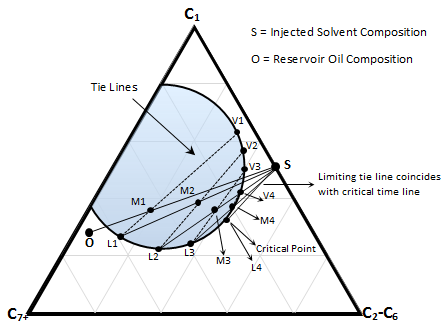
Figure 5-19: Schematic Condensing Gas Drive
Suppose crude oil ‘O’ and injection solvent ‘S’ (Figure 5‑19) are on opposite side of the critical tie line but reversed from the vaporizing gas drive (Figure 5‑16). Oil and injected fluid are not miscible initially as the dilution straight line between them pass through the two phase region. M1 is the first mixture resulted after first contact of ‘S’ and ‘O’. M1 will split to liquid L1 and gas V1 that are in equilibrium at this point in the reservoir. The liquid phase L1 is richer in intermediate components than the original oil ‘O’. Gas phase V1 move faster because of its higher mobility and leaves oil phase L1 to mix with the fresh fluid injected ‘S’ and form mixture M2. The new mixture will split to liquid L2 and gas V2. Liquid L2 lies closer to the critical (plait) point than L1 and is richer in intermediate components. The gas passes the liquid phase and L2 contact with the fresh solvent to form M3 and so forth. By continuing injection of the solvent ‘S’ the composition of the liquid phase is altered progressively in a similar manner along the bubble point curve until it reached the critical point. The plait point fluid is directly miscible with injection fluid ‘S’. the limiting tie line in this process pass through the solvent composition ‘S’ (in contrast to the VGD that pass through the oil composition), so the MMP in this process is defined as the pressure at which the critical tie line coincides with limiting tie line and its extension passes through the solvent composition (Figure 5‑18.a).
[fusion_builder_container hundred_percent=”yes” overflow=”visible”][fusion_builder_row][fusion_builder_column type=”1_2″ last=”no”]
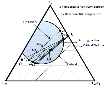
Figure 5-20: Schematic of an Immiscible Displacement
[/fusion_builder_column]
[fusion_builder_column type=”1_2″ last=”yes”]
For dynamic miscibility to be achieved by the condensing-gas drive method with an oil whose composition lies to the left of the critical tie line, the enriched gas composition must lie to the right of the critical tie line. If a gas injected contains less intermediate hydrocarbon so that both oil and solvent compositions located on two phase side of the critical tie line the oil cannot be enriched to the point of miscibility. In Figure 5‑20 enrichment of the liquid phases (L1, L2,…) continue till a point that resulted mixture lie on the tie line that pass through the injected solvent composition point ‘S’. Enrichment will stop at this point. For this system miscibility can be achieved by raising the pressure to shrink the phase envelop so that the limiting tie line coincide with the critical tie line (Figure 5‑18.a).
[/fusion_builder_column]
The original oil composition has no effect on achieving the miscibility state in the condensing gas drive. This process (CGD) is controlled by the injection gas composition.
Two variables can be adjusted in condensing gas drive to achieve miscibility: reservoir pressure and injection solvent composition. The effect of reservoir pressure and MMP concept was explained before (Figure 5‑18). There is an alternative to achieve miscibility in the condensing gas drive process. The injection gas composition can be enriched to achieve miscibility. Minimum Miscibility Enrichment (MME) is defined as the minimum enrichment level which the critical tie line passes through the injection gas composition (Figure 5‑21)
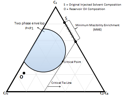
Figure 5-21: Schematic Concept of Minimum Miscibility Enrichment (MME)
Example 5‑4 [fusion_builder_column type=”1_1″ background_position=”left top” background_color=”” border_size=”” border_color=”” border_style=”solid” spacing=”yes” background_image=”” background_repeat=”no-repeat” padding=”” margin_top=”0px” margin_bottom=”0px” class=”” id=”” animation_type=”” animation_speed=”0.3″ animation_direction=”left” hide_on_mobile=”no” center_content=”no” min_height=”none”][50]
A miscible displacement is to be considered for the system described on the pseudoternary diagram in (Figure 5‑22), which is based on mole fraction. The oil composition is shown on the diagram. The injection fluids being considered are C1 and enriched C1 with C2 through C6 components. The injected-fluid cost increases with increasing amount of C2 through C6. Pressure is fixed.
Figure 5-22: Pseudoternary Diagram
Specify the composition of the minimum cost injection fluid that could be used in an MCM process. Use ternary diagram to describe the mechanism for development of miscibility.
Solution
As described before to have a MCM the injection gas and original oil composition points should be on the different sides of the critical tie line. So the miscibility will not improve between pure C1 and reservoir oil, VGD or CGD. So the injected the C1 should be enriched with C2-C6 components till the injection gas and reservoir oil compositions lie on different side of the critical tie line. The less expensive injection gas that could be miscible with oil is a gas that its composition is located exactly on the critical tie line (Figure 5‑23.a). This gas has the minimum C2-C6 concentration that is needed to reach miscibility with oil during MCM. The oil composition is on the left hand side of the critical tie line, so it is not rich in intermediate components to vaporize to the injected gas (VGD). Therefore miscibility would be reached during a condensing gas drive that the intermediate components would condense to the oil (Figure 5‑23.b).
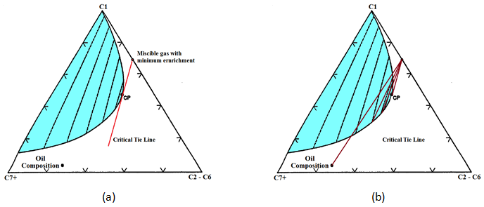
Figure 5-23: Example 5-4
Actual dynamic or multicontact phase behavior may be more complicated than shown in the simple pseudoternary diagram of Figure 5‑19. As discussed before if the composition of pseudo component at different phases changes (for example the pseudocomponent C7+ content of C6 is different in gas phase and liquid phases) then the pseudoternary diagram for a multicomponent system may be incorrect. So using the ternary diagram for the conceptual discussion of multiple contact miscibility processes is not strictly valid for real reservoir oil. However the basic idea of multiple contact miscibility through mass transfer between the phases and the requirement of achieving the critical composition are valid for real fluid system. Zick (1986) explained the miscible displacement process during the enriched gas injection as follows.
The oil/gas system is assumed to be composed of four groups of components:
- Lean components such as C1, N1, and CO2,
- Light intermediate components like as C2 through C4, which are the enriching components,
- Middle intermediate components which may range from C4 through C10 on the low-molecular weight side up to C30 on the high side that are generally not in the injected gas but in the reservoir oil and may be vaporized from the oil to the gas phase.
- High molecular weight components that cannot be vaporized from the oil in significant amount.
According to Figure 5‑19 explanation when the enriched gas containing the components from group 1 and 2, contacts reservoir oil, light intermediates condense into the oil, making it lighter. The gas moves faster than the oil, so the depleted gas moves ahead. Additional fresh injected gas contact the oil, continuing enriched the oil with intermediate components. This process continues to reach miscibility. But there is a counter effect. The middle intermediate in the oil are stripped from the oil into the gas because this components are not originally in the injected gas. Thus the reservoir oil in contact with the fresh gas initially become lighter, but as it contact more gas and loses only some of its lighter heavies, overall it tends to enriched in very heavy fractions and thus becomes less similar to the injection gas. Figure 5‑24 shows the variation of measured components groups in the oil phase at the injection point for a sample oil. According the previous explanation of the condensing gas drive the concentration of C7+ should be decreased step by step to reach miscibility while experiments shows that an examination of heavy end, e.g. C20+ has increased distinctly due to vaporization of the lighter heavies. This prevents the development of miscibility between injected gas and reservoir oil. If this were all that occurred, the process would not be very efficient. However, downstream of the injection point is a positive mechanism. By continuing injection of the gas upstream oil becomes saturated with the light intermediates and therefore these components do not condense out of the gas into the oil, thus the downstream oil contacts a gas that is rich both in light and middle intermediates. So this gas vaporizes less middle intermediates from the downstream oil while losing intermediate to the downstream oil that is not rich in the intermediate oil. As this process continue and move downstream at a favorable condition the combined vaporizing/condensing process in a state within the transition zone where the compositional path goes through the critical point. In other worlds a gas is resulted that is almost miscible with reservoir oil. This process can be imagined as a combination of the condensing process at the downstream and vaporization at the upstream. This process is called ‘condensing/vaporizing gas drive’.
The reservoirs containing the oil without high concentration of intermediate hydrocarbons are the first nominate for this type of recovery. However this process may be applied to a wide range of crude oil and to reservoirs with pressure of about 1500 psi and greater.
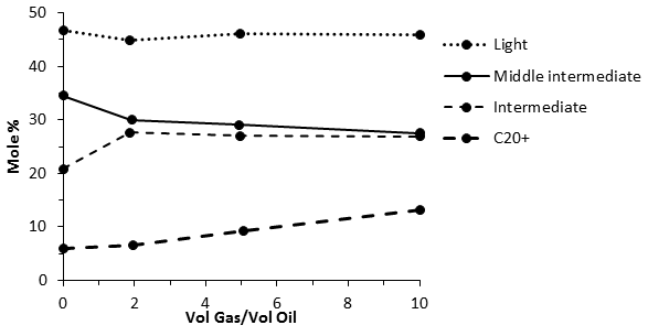
Figure 5-24: Vaporization of Component Groups in Contacted Oil at Injection Point With the Ratio of Injected Volume to Contacted Volume
[fusion_separator top=”25″/]
[fusion_builder_row_inner][fusion_builder_column_inner type=”1_2″ last=”no”]
[/fusion_builder_column_inner]
[fusion_builder_column_inner type=”1_2″ last=”yes”]
EXPERIMENTAL INVESTIGATION OF THE MISCIBILITY EFFECT ON THE FINAL OIL RECOVERY >>
[/fusion_builder_column_inner][/fusion_builder_row_inner]
[fusion_separator top=”35″/]
References
Questions?
If you have any questions at all, please feel free to ask PERM! We are here to help the community.[/fusion_builder_column][/fusion_builder_row][/fusion_builder_container]