
Fundamentals of Fluid Flow in Porous Media
Chapter 5
Miscible Displacement
Determination of Miscibility Condition: Slim Tube Test
It is a laboratory test used to estimate the minimum miscibility pressure (MMP) or minimum miscibility concentration (MMC) of a given injection solvent and reservoir oil. The first slim tube test has been run in the early 1950s. Figure 5‑26 shows a schematic typical slim tube test apparatus. The slim tube is a narrow stainless-steel tube with an internal diameter (ID) of about 5 /16 in. and a length between 5 and 40 meters. The tube is packed with glass beads of a size on the order of 100 mesh or sand of a specific mesh size (the ratio of particle size to tubing diameter is sufficiently small (less than 1 / 10 ) that wall effect can be neglected,), so it is a one dimensional model of the reservoir. “The sand packed tube displacement apparatus is a device for bringing about multiple equilibrium contacts between simultaneous flowing fluids. It is not intended to simulate reservoir conditions. Hence, slim-tube tests should not be indicative of ultimate recovery, macroscopic sweep efficiency, transition zone length, etc., to be achieved in actual reservoir”[fusion_builder_container hundred_percent=”yes” overflow=”visible”][fusion_builder_row][fusion_builder_column type=”1_1″ background_position=”left top” background_color=”” border_size=”” border_color=”” border_style=”solid” spacing=”yes” background_image=”” background_repeat=”no-repeat” padding=”” margin_top=”0px” margin_bottom=”0px” class=”” id=”” animation_type=”” animation_speed=”0.3″ animation_direction=”left” hide_on_mobile=”no” center_content=”no” min_height=”none”][1]. The actual displacement in reservoir is influenced by various mechanisms cause dispersion, such as gravity override caused by gravity effect and viscous fingering caused by unfavorable viscosity ratio and porous medium heterogeneity, while an ideal slim tube should provide a one dimensional dispersion free displacement of oil. At this condition the MMP, MME and the final recovery of the displacement process are only depend on the thermodynamic phase behavior of the system.
The tube is coiled in a manner so that flow is basically horizontal and the gravity effects are in significant. The coiled tube is placed inside a constant temperature bath.
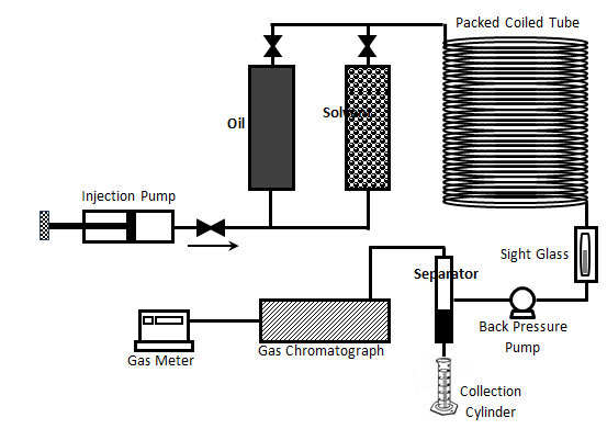
Figure 5-26: Schematic Diagram of Slim Tube Apparatus
To do the test, the porous medium in the tube is initially saturated with reservoir sample oil. The coiled tube is maintained at the reservoir temperature using the bath and the pressure is set at a pressure higher than the bubble point pressure. The oil then displaced by injecting solvent into the tube at a constant inlet, or often outlet pressure, that is controlled by back pressure regulator. The pressure drop across the coiled tube is generally a small fraction of the applied pressure on the system, so the entire displacement pressure is considered to be at a single constant pressure.
Effluent production, density and composition are measured as functions of the injected volume. As mentioned before by eliminating the dispersion final recovery if a function of thermodynamic phase behavior. Therefore the miscibility conditions are determined by conducting the displacement at various pressure, or injection solvent enrichment levels and monitor the oil recovery. The recoveries are then plotted as a function of displacement pressure, or solvent enrichment level. By increasing the pressure (using back pressure regulator) final recovery increases. This recovery increment is considerable for the pressure lower than the MMP, but for the pressure higher than MMP incremental oil recovery by increasing the pressure is not significant, in other worlds additional recovery above MMP is generally minimal. Based on this observation, MMP could be determined as the pressure at the “break” in the curve (Figure 5‑27.a). In other words MMP has been chosen as the pressure for which incremental oil recovery per incremental pressure increase is less than some arbitrary value. Some researchers define MMP as the pressure when the oil recovery is 90 or 95 percent. The same observation could be seen during the displacement of oil with the solvent at different enrichment levels. The final oil recovery increases significantly by increasing the injection solvent enrichment level. But the recovery increment ceased after a specified enrichment level (MME), see Figure 5‑27.b. Enrichment level is changed by altering the intermediate hydrocarbon component concentration such as C2+ in the displacing solvent.
Visual observation of the flow through a sight glass placed at the coiled tube outlet (Figure 5‑26) could help in determination of miscibility condition. The achievement of miscibility is expected to accompany a gradual change of color of the flowing fluid from that of the oil to clear gas. On the other hand, observation of two phase flow is symptomatic of an immiscible displacement. Effluent fluid is cooled and the separated gas is evaluated by a gas chromatograph (Figure 5‑26).
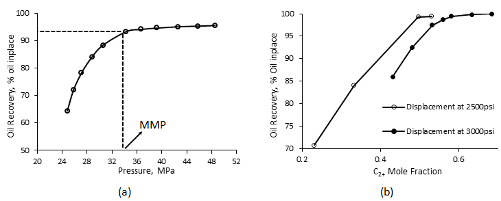
Figure 5-27: a) Slim Tube Recovery versus Applied Pressure, b) Slim Tube Recovery as a Function of Solvent Enrichment[2]
Using a long tube has an additional rationale. The gravity segregation has an adverse effect on the displacement recovery results, and unstable flow occurs in the early stage of the displacement. Overly stabilized flow could be achieved by increasing the length of the model, so the use of longer slim tubes yields the best estimate of the MMP and MME.
Experiments show that final recovery increases by increasing the slim tube length for any injection rate. As previously explained a multi contact miscibility starts as an immiscible displacement. Miscibility achieved through multi contact between the injection and in place fluids which implies that the solvent at the front has to contact enough fresh oil or travel a minimum distance before miscibility is achieved. Dispersion caused by viscous fingering or permeability heterogeneity increases the minimum length requirement to accomplish miscibility. Total recovery is the sum of the recovery obtained while solvent travels the immiscible portion of the tube and the recovery obtained while solvent travels the miscible portion of the tube[3]:
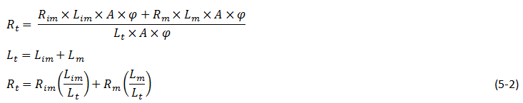
Where,
A = Cross section area of the slim tube,
φ = Average porosity,
Rt = Total recovery,
Rim = Recovery in the immiscible portion of the displacement,
Rm = Recovery in the miscible portion of the displacement,
Lim = Immiscible portion length,
Lm = Miscible portion length,
Lt = Total slim tube length.
The Lim is independent of the overall length of the tube so according to eq. (5‑2) the final recovery approaches to the miscible recovery by increasing the slim tube length.
As mentioned increasing the length stabilizes displacement and this stabilizing effect is rate independent. So as long as the length of the system is sufficiently long the rate of injection is not critical, however a moderately high injection rate is preferable in order to obtain a better differentiation between immiscible and MCM displacement.
It can be concluded that except some criteria there is no standard design, no standard operating procedure, and no standard criterion for determining MMPs and MMEs with the slim tube. Also slim tube test is a time consuming method. While each displacing run under specific pressure takes about one day, one or two days are needed to clean and re-saturate the slim tube. So determination of MMP or MME for an oil-solvent system takes at least one week.
Example 5‑5
A CO2 displacement test is conducted in a slim tube apparatus. A pseudoternary phase diagram for the fluid system is shown. The oil composition is indicated on the diagram. A displacement test is conducted with a fluid that is 96% CO2 and 4% C2-C6.
- Will the miscibility achieved in this displacement?
- When the injection gas first break through at the exit end of the slim tube what will its composition be?
- Consider a location near the entrance of the slim tube. Several PV,s of the gas will have flowed through this position by the end of the run. What will be the final oil composition at this position near the entrance?
Solution
[…] TO BE ADDED
[fusion_separator top=”25″/]
[fusion_builder_row_inner][fusion_builder_column_inner type=”1_2″ last=”no”]
<< DETERMINATION OF MISCIBILITY CONDITION
[/fusion_builder_column_inner]
[fusion_builder_column_inner type=”1_2″ last=”yes”]
RISING BUBBLE APPARATUS (RBA) >>
[/fusion_builder_column_inner][/fusion_builder_row_inner]
[fusion_separator top=”35″/]
References
[1] “Parametric Analysis On The Determination Of The Minimum Miscibility Pressure In Slim Tube Displacements”, Flock, D.L. and Nouar, A., JCPT, 1984
[2] “An Interpretation of the Displacement Behavior of Rich Gas Drives Using an Equation-of-State Compositional Model”, Mansoori, J. and Gupa, S.P., SPE No. 18061, 1988
[3] “A Laboratory Investigation of Miscible Displacement by Carbon Dioxide”, Rathmell, J.J., Stalkup, F.I., SPE No. 3483, 1971
Questions?
If you have any questions at all, please feel free to ask PERM! We are here to help the community.[/fusion_builder_column][/fusion_builder_row][/fusion_builder_container]