
Fundamentals of Fluid Flow in Porous Media
Chapter 2
Multi-phase Saturated Rock Properties:
Phase Trapping: Jamin Effect
The Jamin Effect[fusion_builder_container hundred_percent=”yes” overflow=”visible”][fusion_builder_row][fusion_builder_column type=”1_1″ background_position=”left top” background_color=”” border_size=”” border_color=”” border_style=”solid” spacing=”yes” background_image=”” background_repeat=”no-repeat” padding=”” margin_top=”0px” margin_bottom=”0px” class=”” id=”” animation_type=”” animation_speed=”0.3″ animation_direction=”left” hide_on_mobile=”no” center_content=”no” min_height=”none”][1] is defined as that resistance to liquid flow through capillaries which is due to the presence of bubbles. Presence of bubbles can retard the flow of a liquid as it progresses through a capillary tube of small diameter. The Jamin effect may be defined as that resistance to flow under pressure through a capillary tube which is encountered by liquid globules interspaced with large bubbles. This effect or action is a phenomenon quite apart from frictional resistance and is due to difference of capillary pressure between two sides of the trapped globule. This effect can be described more easily by analyzing a trapped oil droplet or gas bubble in a preferentially water wet capillary tube.
In Figure 2‑72 assume the system is static with different pressure existence between point A and B because of capillary forces. The static pressure difference must be exceeded for flow to occur, in other words the static pressure difference, PA – PB, must be overcome to initiate flow. In Figure 2‑72.a the capillary tube size varies and therefore the radius is smaller on one side of the drop than on the other. Figure 2‑72.b shows a situation that the contact angle is different on the two sides of the drop, which could result, for example, if the drop displaced in one direction that there will have one Advancing contact angle and one Receding. In Figure 2‑72.c a gas drop is trapped between water and oil. An assumption is made that the pressure within the oil or gas drop is constant from one end to the other end of drop. With this assumption we have
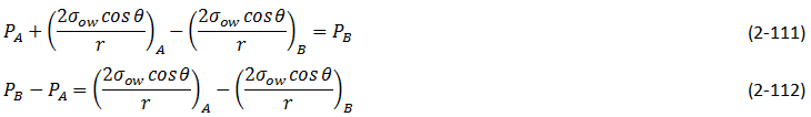
Subscripts A and B are the values are determined for the interfaces at point A and B.
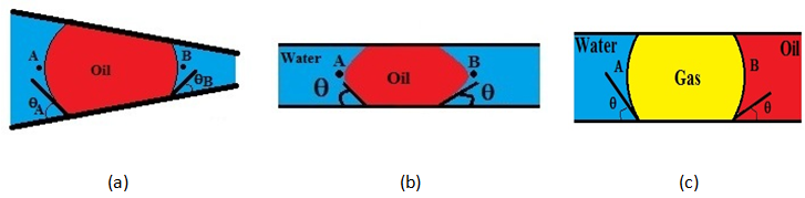
Figure 2-72: Trapping of a Droplet in a Capillary Tube
Application of this equation in Figure 2‑72.a, b, c yields the following forms.
Figure 2‑72.a: Assume θA = θB the pressure difference at static condition is

If rA > rB then PA > PB and a pressure drop exists in the direction from point A to point B. this gradient would have to be exceeded to induce flow into the narrower part of the capillary constriction.
Figure 2‑72.b:

For an advancing contact angle at point B and a receding at point A, θA > θB and cosθA < cosθB. Again PA > PB and a pressure gradient exist in the potential direction of flow at static, or trapped, condition.
Figure 2‑72.c:

In this case IFT and contact angles are different at the two interfaces because of different fluid systems. If σgwcosθA < σgocosθB a pressure drop exists from point A to point B when this system is static.
[fusion_separator top=”25″/]
[fusion_builder_row_inner][fusion_builder_column_inner type=”1_2″ last=”no”]
<< BYPASSING
[/fusion_builder_column_inner]
[fusion_builder_column_inner type=”1_2″ last=”yes”]
AVERAGING CAPILLARY PRESSURE DATA (LEVERETT J-FUNCTION) >>
[/fusion_builder_column_inner][/fusion_builder_row_inner]
[fusion_separator top=”35″/]
References
Questions?
If you have any questions at all, please feel free to ask PERM! We are here to help the community.[/fusion_builder_column][/fusion_builder_row][/fusion_builder_container]