
Fundamentals of Fluid Flow in Porous Media
Chapter 2
Multi-phase Saturated Rock Properties:
Phase Trapping: Bypassing
According to the Pc equation, at the same condition non-wetting phase tends to invade the larger pores because of the lower capillary pressure. This tendency leads to special trapping mechanism named bypassing. The main trapping mechanism in drainage is bypassing although during the imbibition process non-wetting phase could be trapped by bypassing mechanism but it is not the major trapping mechanism.
A reservoir rock consists of a complex network of branching and reuniting pore elements of differing sizes and geometry. Any successful analysis of the displacement process should eventually recognize this complex network. However one can begin by understanding the processes which take place in the simpler elements of the network. The mechanisms of drainage displacement and imbibition displacement are best illustrated by visualization of flow experiments in transparent capillary networks etched on glass plates. The simplest type of pore system used in such displacement studies is the pore doublet (Figure 2‑69).
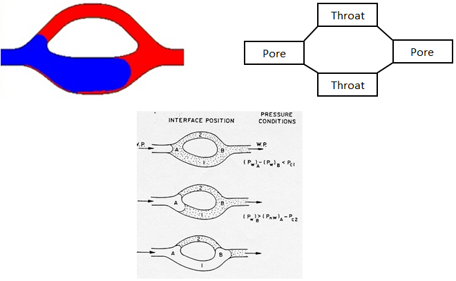
Figure 2-69: Pore Doublet Model
Smaller throat is invaded first during the imbibition because of higher capillary pressure and larger throat is swept first during the drainage process.
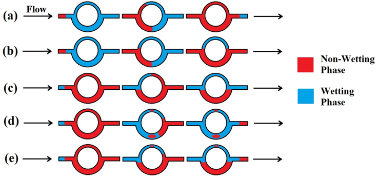
(a) Drainage Process, No Trapping
(b) Drainage Process, Bypassing in Smaller Throat
(c) Imbibition Process, Bypassing in Larger Throat
(d) Imbibition Process, Snap-Off
(e) Imbibition Process, Snap-Off in Smaller Throat and Bypassing in Larger Throat
Figure 2‑70 illustrates the drainage and imbibition mechanisms for the pore doublet model.
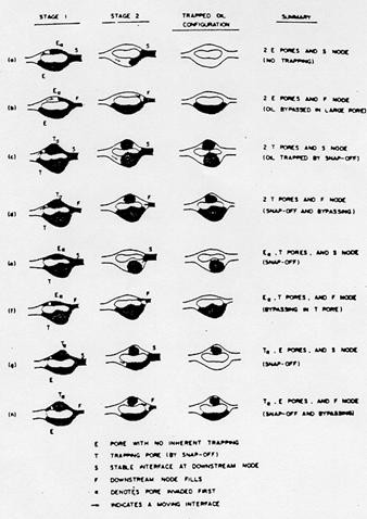
Figure 2-70: Imbibition and Drainage Mechanisms in a Pore Doublet Model
The condition that bypassing happen in the larger pore during the imbibition could be found by using the capillary and viscous forces formula.
[fusion_builder_container hundred_percent=”yes” overflow=”visible”][fusion_builder_row][fusion_builder_column type=”1_2″ last=”no”]
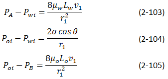
Assume a pore doublet model as in Figure 2‑71.
For pore #1:
[/fusion_builder_column]
[fusion_builder_column type=”1_2″ last=”yes”]
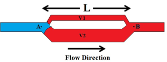
Figure 2-71: Pore Doublet Model for Illustration of Displacement and Trapping of Oil[1]
[/fusion_builder_column]
Assume μw = μo = μ and defining L = Lo + Lw, we get

Similarly for second pore:

The overall pressure change is same for both pores, therefore:

This equation gives a relationship between v1 and v2:

For v2 to be positive (no trapping by bypassing), we must satisfy

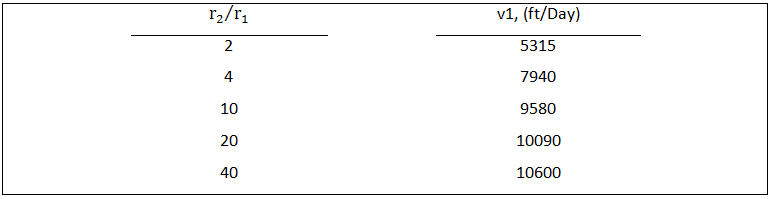
The values of v1 needed to make v2 positive are listed in Table 5 for a typical case. At reservoir type velocities, v2 will not be positive and oil will be displaced only from the smaller pore. Once the water breaks through at the other end of the pore doublet, the oil in the larger pore is trapped and very difficult to mobilize.
Table 5: Pore Doublet Model, Required Velocity in Small Pore to Maintain Zero Velocity in Large Pore (r1=2.5μm)
Other pore space models used to understand displacement mechanisms are:
- bundle of tubes
- network
- contact angle
[fusion_builder_column type=”1_1″ background_position=”left top” background_color=”” border_size=”” border_color=”” border_style=”solid” spacing=”yes” background_image=”” background_repeat=”no-repeat” padding=”” margin_top=”0px” margin_bottom=”0px” class=”” id=”” animation_type=”” animation_speed=”0.3″ animation_direction=”left” hide_on_mobile=”no” center_content=”no” min_height=”none”][fusion_separator top=”25″/]
[/fusion_builder_column][fusion_builder_column type=”1_2″ last=”no”]
<< SNAP-OFF
[/fusion_builder_column]
[fusion_builder_column type=”1_2″ last=”yes”]
JAMIN EFFECT >>
[/fusion_builder_column]
[fusion_builder_column type=”1_1″ background_position=”left top” background_color=”” border_size=”” border_color=”” border_style=”solid” spacing=”yes” background_image=”” background_repeat=”no-repeat” padding=”” margin_top=”0px” margin_bottom=”0px” class=”” id=”” animation_type=”” animation_speed=”0.3″ animation_direction=”left” hide_on_mobile=”no” center_content=”no” min_height=”none”][fusion_separator top=”35″/]
References
[/fusion_builder_column][fusion_builder_column type=”1_1″ background_position=”left top” background_color=”” border_size=”” border_color=”” border_style=”solid” spacing=”yes” background_image=”” background_repeat=”no-repeat” padding=”” margin_top=”0px” margin_bottom=”0px” class=”” id=”” animation_type=”” animation_speed=”0.3″ animation_direction=”left” hide_on_mobile=”no” center_content=”no” min_height=”none”][1] Willhite (1986)
Questions?
If you have any questions at all, please feel free to ask PERM! We are here to help the community.[/fusion_builder_column][/fusion_builder_row][/fusion_builder_container]