
Fundamentals of Fluid Flow in Porous Media
Chapter 5
Miscible Displacement
Determination of Miscibility Condition: Rising Bubble Apparatus (RBA)
Christiansen and Haines, designed and made the RBA as a reliable, fast alternative to a slim tube for measuring MMP[fusion_builder_container hundred_percent=”yes” overflow=”visible”][fusion_builder_row][fusion_builder_column type=”1_1″ background_position=”left top” background_color=”” border_size=”” border_color=”” border_style=”solid” spacing=”yes” background_image=”” background_repeat=”no-repeat” padding=”” margin_top=”0px” margin_bottom=”0px” class=”” id=”” animation_type=”” animation_speed=”0.3″ animation_direction=”left” hide_on_mobile=”no” center_content=”no” min_height=”none”][1]. The observation of a gas bubble behavior that rises in a visual high pressure cell filled with reservoir oil is the base of this method.
The major part of the RBA is a flat glass tube stands vertically in a high pressure sight gauge in a temperature controlled bath. The glass tube is flat for better viewing of bubbles rising in opaque oils. The sight gauge is backlighted for visual observation and photography of rising bubbles in the oil. The gas bubble is injected into the glass tube through a hollow needle that is mounted at the bottom of sight gauge. As the first step of the test the sight gauge and glass tube are filled with distilled water. In the next step, enough oil is injected into the glass tube to displace all but a short column of water in to the tube’s lower end (Figure 5‑28). Next, a small bubble of gas of the desired composition is launched into the water. The buoyant force on the bubble caused it to rise through the column of water then through the water-oil interface. As the bubble rises through the oil, its shape and motion are observed and photographed. After that the bubble rises through the oil the used oil is replace with fresh oil and the test run again at different pressure or with different injection gas composition.
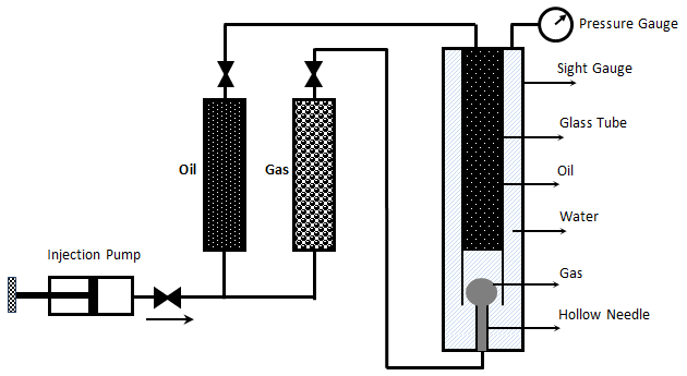
Figure 5-28: Oil, Water and Gas in RBA at Start of Test
It is assumed that the mass transfer process that occurs as the gas bubble rises through the oil in the glass tube is similar to the MCM process that occurs in a slim tube test. During the rising of the bubble through the oil at each height it faces fresh oil and the gas bubble enriched with intermediate components as rise through the column, same mechanism that we have during vaporizing gas drive. According to Figure 5‑17, if the compositions of the gas bubble and oil are on the same side of the critical tie line, miscibility cannot be achieved. By increasing the pressure two phase region in the ternary diagram shrinks and for pressure above the MMP with some oil-gas pairs, it is possible for the two phase region to be so small that the gas and oil are first contact miscible.
[fusion_builder_row_inner][fusion_builder_column_inner type=”1_4″ last=”no”]
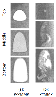
Figure 5-29: Bubble Behavior of Vaporizing Gas Process[2]
[/fusion_builder_column_inner]
[fusion_builder_column_inner type=”3_4″ last=”yes”]
- At pressure far below MMP, the bubble retains its almost spherical shape, but its size is reduced as the gas is partially dissolved in the oil, Figure 5‑29.a. As the pressure approaches MMP, a bubble still remains nearly spherical on top, but the bottom interface of the bubble changes from spherical to flat or “wavy”.
- At or slightly above MMP tail-like features quickly developed on the bottom of a rising bubble, which remain spherical on top. The gas-oil interface vanishing from the bottom of the bubble, Figure 5‑29.b. This behavior is a result of multi contact miscibility process. During this MCM process the volume of the bubble is almost constant until the interface starts to deteriorate.
- At pressure higher than MMP, the bubble disperses very rapidly and disappears into the oil. It should be consider that a gas bubble could disappear into an undersaturated oil without achieving miscibility, but at this condition it will not disperse before disappearing.
[/fusion_builder_column_inner][/fusion_builder_row_inner]
In addition to injection of lean gas and simulate the vaporizing gas drive with RBA, the condensing gas process could be happened during a RBA test by injecting several enriched gas bubbles sequentially to the oil filled glass tube. The evolution of bubble shape during the condensing gas process is different compare to the vaporizing gas process:
[fusion_builder_row_inner][fusion_builder_column_inner type=”1_4″ last=”no”]
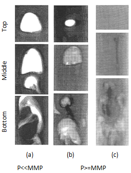
Figure 5-30: Bubble Behavior for Condensing Gas Drive[2]
[/fusion_builder_column_inner]
[fusion_builder_column_inner type=”3_4″ last=”yes”]
Far below the MMP, the shape evolution of injected bubbles are similar and indicate low interfacial tension when the bubbles first contact the oil (they are enriched gas bubbles with a considerable intermediate hydrocarbon components), after rising a short distance through the oil, the bubble shape evolves to indicate high interfacial tension (the bubbles lost a major part of their intermediate hydrocarbons), Figure 5‑30.a. At or above MMP bubbles at different injection sequence shows different shape evolution. The first bubble show the same shape evolution as in P < MMP. It evolves from a shape indicating low interfacial tension to a shape indicating high interfacial tension. But, with each additional bubble injected (the oil sequentially is enriched with intermediate hydrocarbon that condensed from the gas bubble) the size of the bubble which emerges from the swirl of gas and oil at low interfacial tension, shrinks, Figure 5‑30.b. After of injecting several bubbles the injected bubble disappears as injected to the oil (the oil is enriched in intermediate hydrocarbon and become miscible with the injected gas), Figure 5‑30c.
[/fusion_builder_column_inner][/fusion_builder_row_inner]
This test is completely qualitative in nature and the miscibility is simply inferred from visual observations. Hence, some subjectivity is associated with the miscibility interpretation of this technique, as it lacks quantitative information. Therefore, the results obtained from this test are somewhat arbitrary, however the RBA approach to measuring MMP’s is much more rapid ( it requires less than 2 hours to determine miscibility) than the commonly accepted slim tube techniques. This method is also cheaper and requires smaller quantities of fluids, compared to slim-tube. The main disadvantages associated with this technique are[3]:
- The subjective interpretation of miscibility from visual observations
- Lack of any quantitative information to support the results
- Some arbitrariness associated with miscibility determination
While there are many more slim tube apparatus in industry, a larg portion of MMPs reported in the literature were measured using RBA method.
[fusion_separator top=”25″/]
[fusion_builder_row_inner][fusion_builder_column_inner type=”1_2″ last=”no”]
[/fusion_builder_column_inner]
[fusion_builder_column_inner type=”1_2″ last=”yes”]
SLIM TUBE TEST VERSUS RBA METHOD >>
[/fusion_builder_column_inner][/fusion_builder_row_inner]
[fusion_separator top=”35″/]
References
[1] “Rapid Measurement of Minimum Miscibility Pressure with the Rising-BubbIe Apparatus”, Christiansen R. L. and Haines H. K., SPE No. 13114, 1987
[2] “Measuring Minimum Miscibility Pressure: Slim-Tube or Rising-Bubble Method?”, Elsharkawy A.M., Suez Canal U., Poettmann F.H. and Christianse R.L., SPE no. 24114, 1992.
[3] “Measurement and Modeling of Fluid-Fluid Miscibility in Multicomponent Hydrocarbon Systems”, Ayirrala S. C., 2005
Questions?
If you have any questions at all, please feel free to ask PERM! We are here to help the community.[/fusion_builder_column][/fusion_builder_row][/fusion_builder_container]