Fundamentals of Fluid Flow in Porous Media
Chapter 2
Porosity
The rock texture consists of mineral grains of various shapes and sizes and its pore structure is extremely complex. The most important factors of the pore structure are how much space there is between these grains and what their shapes are. That is because the spaces between these grains serve to either mainly transport fluids forming connecting pores, or to store the fluids forming storage pores.
From the reservoir engineering standpoint, porosity is one of the most important rock properties, a measure of space available for storage of hydrocarbons. Quantitatively, porosity is the ratio of the pore volume to the total volume (bulk volume). This important rock property is determined mathematically by the following generalized relationship (Figure 2‑3):

bulk volume = grain volume + pore volume
Where φ = porosity
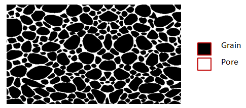
Figure 2-3: Microscopic Cross Section Image of a Porous Medium
As the sediments were deposited and the rocks were being formed during geological times, some void spaces that developed became isolated from the other void spaces by excessive cementation. Thus, many of the void spaces are interconnected while some of the pore spaces are completely isolated. This leads to two distinct types of porosity, namely:
- Absolute porosity
- Effective porosity
Absolute porosity
The absolute porosity is defined as the ratio of the total pore space in the rock to that of the bulk volume. A rock may have considerable absolute porosity and yet have no conductivity to fluid for lack of pore interconnection. The absolute porosity is generally expressed mathematically by the following relationship:

Where φa = absolute porosity.
Effective porosity
From the standpoint of flow through a porous medium only interconnected pores are of interest, hence the concept of effective porosity defined as the percentage of interconnected pore space with respect to the bulk volume, or

Where φe = effective porosity.
The effective porosity is used in all reservoir engineering calculations because it represents the interconnected pore space that contains the recoverable hydrocarbon fluids. Transportation of fluids is controlled mainly by connected pores. For intergranular materials, poorly to moderately well cemented, the total porosity is approximately equal to effective porosity. For more cemented materials and some carbonates, significant difference in total porosity and effective porosity values may occur. Another type of pores that seem to belong to the class of interconnected pores but contribute very little to the flow, are dead-end pores or stagnant pockets (Figure 2‑4). These pores have just a constricted opening to the flow path so the fluid in them is practically stagnant. In certain mechanisms of flow such as diffusion and dispersion it is important to pay attention to the effects of dead-end pores.
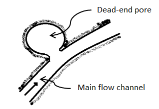
Figure 2-4: Dead-end Pores
A pore-structure concept for rocks (Figure 2‑5) was presented (Katsube and Collett, 1973) in the 1970s, which consisted of total connecting porosity (φC) for connecting pores that contribute mainly to fluid migration and of storage porosity (φS) for storage pores that contribute mainly to fluid storage, where their sum is effective porosity (φe):
φS + φC = φe (2-4)
The storage pore shapes can be characterized by vugular or intergranular, as shown in Figure 2‑5.
There are two major types of connecting pores: sheet-like, circular and/or tubular pores. Many more types of connecting pores can be considered, but these are most representative for describing the extreme differences between their types. For example, the cross-section of connecting pores can have many shapes (Figure 2‑6). A representative cross-section of a sheet-like pore is shown in Figure 2‑6.a. Cross-sections of circular and/or tubular pores can take many shapes (Figure 2‑6.b). The total connecting porosity (φC) value of a rock includes connecting pores in all three directions (Figure 2‑7.a). However, when considering fluid or electrical current flow through the rock, only pores in two directions are considered for sheet-like pores (Figure 2‑7.a), and only in one direction for circular and/or tubular pores (Figure 2‑7.b). The fluid flow in a rock is controlled mainly by connecting pores. The term “connecting pores” implies all pores except for isolated pores. However, some of these connecting- or storage- pore systems can be dead-end. The connecting pores that contribute to electrical current- or fluid flow through the rock have to be interconnected from one end of the rock to the other, and not include dead-end pores. These are distinguished as end-to-end connecting pores. The actual porosity of the end-to-end connecting pores should be smaller than the value of φC, since it does not include the porosity of the dead-end pores. The storage-connecting pore system and its porosity descriptions are shown in Figure 2‑7.b for a rock section that includes vugular storage and isolated pores. The end-to-end connecting porosity of the pore system in Figure 5 is represented by φCF. Where: Porosity may be classified according to the mode of origin as “original” and “induced”. The original porosity is that developed in the process of deposition that forms the rock, while induced or secondary porosity added at a later stage by some geologic and chemical process. The inter-granular porosity of sandstones and the inter-crystalline and oolitic porosity of some limestones typify original porosity. Induced porosity is typified by fracture development as found in shales and limestones and by the vugs or solution cavities commonly found in limestones. Rocks having original porosity are more uniform in their characteristics than those rocks in which a large part of the porosity is included. Materials having induced porosity such as carbonate rocks have complex pore configuration. In fact two or more systems of pore openings may occur in such rocks. The basic rock material is usually finely crystalline and is referred to as the matrix. The matrix contains uniformly small pore openings which comprise one system of pores. One or more systems of larger openings usually occur in carbonate rocks as a result of leaching or fracturing of the primary rock material. Fractures and vugs are highly variable in size and distribution. Therefore even more than for intergranular materials, laboratory measurements are required for quantitative evaluation of porosity. For direct quantitative measurement of porosity, reliance must be placed on formation samples obtained by coring. Many porous media are made of discrete large and small grains or particles that are loose (unconsolidated porous media). Consolidated sedimentary rocks are derived from initially unconsolidated grains that have gone significant cementation at areas of grain contact. Early investigations of the porosity were conducted to a large extend by investigation in the fields of ground water geology, chemical engineering, and ceramics. Therefore much interest was centered on the investigation of the porosity of unconsolidated materials. The porosity of unconsolidated materials depends on: The porosity of consolidated materials depends mainly on the degree of cementation and consolidation but also on the above mentioned parameters. Consider simple models, such as a regular packing of uniform sphere or rods. Graton and Fraser (1935) analyzed the porosity of variable packing arrangements of uniform spheres. The least compact arrangement of uniform spheres is that of cubical packing with a porosity of 47.6%. The most compact packing of uniform spheres is the rhombohedra or close-packed, where the porosity is 26.0%. In these and other cases of sphere of equal size, the porosity is independent of the radius of spheres. Cross view of the unit cell of two of the mentioned packing are shown in Figure 2‑8. Often porous materials with spherical grains have lower porosity than materials composed of non-spherical grain. Example 2‑1 Calculate the cubic packing of uniform spheres porosity (Figure 2‑8). Solution The unit cell is a cube with sides equal to 2r where r is the radius of sphere. Therefore Bulk volume = (2r)3 Since there are 8 (1/8) spheres in the unit cell Grain volume = 8 x (1/8) x ((4πr3)/3) The porosity is therefore is The interesting point is that the radii cancel in the formula and the porosity of packing uniform spheres is a function of packing only. Naturally occurring materials are composed of a variety of particle sizes. The particle size distribution may appreciably affect the resulting porosity, as small particles may occupy pores formed between large particles, thus reducing the porosity (Figure 2‑9-a). On the other hand sometimes porosity increases during a phenomenon called bridging (Figure 2‑9-b). In naturally occurring materials porosity increases by decreasing the grain sizes. An increase in range of particle size tends to decrease porosity. During the cementation process in consolidated rocks as the pore space is filled with cementing material, significant reduction in porosity may take place. Because compaction forces vary with depth, porosity will also vary with depth especially in clays and shales. Krumbein and Sloss (1951) indicate a reduction in sandstone porosity from 52 to 41% and in shale from 60 to 6% as depth increases from 0 to 2000m. Most of the pore reduction is due to the inelastic, hence irreversible, effects of intergranular movement. Reservoir rocks may generally show large variations in porosity vertically but do not show great variations in porosity parallel to the bedding planes. If you have any questions at all, please feel free to ask PERM! We are here to help the community.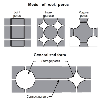
Figure 2-5: Storage and connecting pore model for shale or any other type of rock with interconnected pore systems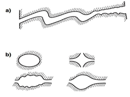
Figure 2-6: The Various Cross-Sections of Connecting Pores: a) Tortuous Sheet-Like Pore; b) Various Shapes of Tubular Pores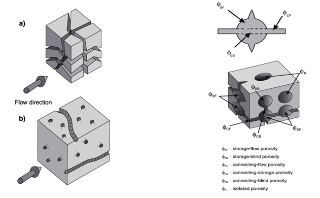
Figure 2-7: a) Three-dimension distribution of connecting; b) Complete storage-connecting pore system.[2]
φT = φe + φisolated
Total Porosity
,φSF
Storage flow porosity
φe = φS + φC
Effective Porosity
,φSB
Storage blind (Dead-end) porosity
φs = φSF + φB
Storage porosity
,φCF
Connecting flow porosity
φB = φSB + φCB
Blind porosity
,φCS
Connecting storage porosity
φC = φ + φCS
Connecting porosity
,φCB
Connecting blind porosity
Grain shape and packing
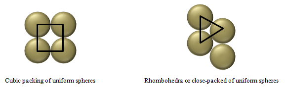
Figure 2-8: Typical ordered porous medium structures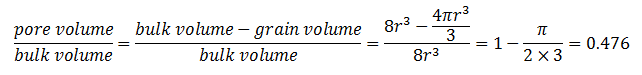
Grain size distribution and grain sorting
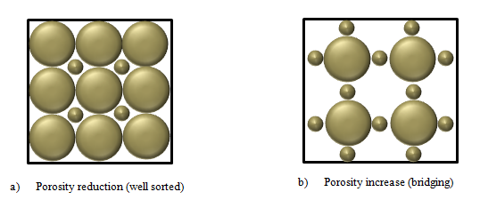
Figure 2-9: Effect of sorting and grain size distribution on porosityCementation and compaction
References
Questions?