Fundamentals of Fluid Flow in Porous Media
Chapter 3
Diffusion Coefficient: Measurement Techniques
Computer-Assisted Tomography: Diffusivity Investigation
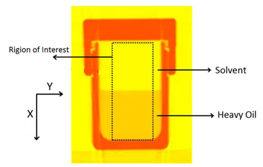
Wen and Kantzas The two-dimensional CT image shows the diffusion process along the vertical direction (x axis) of length of the diffusion cell. A central area (region of Interest, ROI) is cut as shown by a dotted line in Figure 3‑24. The ROI is used for diffusion coefficient calculation and analysis. This study considers the diffusion process as a one-dimensional vertical diffusion process. Therefore, only an average CT number in the horizontal direction is calculated to represent the CT number in the center, and then the profile of CT numbers change with vertical distance for each “x” value is obtained. The changes in the CT numbers are related to the changes of oil densities as a solvent diffuses into the heavy oil, and CT number has a linear relationship with density. Thus, the CT number profiles can be converted to the density profiles. In addition, the mixture (solvent and heavy oil) density has a linear relation with the solvent content in the mixture. Therefore, using the following equation (eq. ((3‑47)), normalized concentration profiles could be obtained from the densities. Where: c / co = Normalized Concentration (volume fraction), ρ = Bulk oil density (kg/m3), ρo = Density of the solvent close to the interface (kg/m3) ρoil = Initial Density of the oil (kg/m3) By assumption of linear relationship between concentration and diffusion coefficient[2] the Fick’s second law equation (eq. (3‑22)) could be converted to the following equation: Using CAT scanning we have density at each point for any measurement time. This was the base idea for Guerrero-Aconcha and Kantzas[3] to find diffusion coefficient as a function of concentration. They assume that the diffusion process is in the x direction and at each cross section there is a uniform concentration. They divided the diffusion length to several control volumes and discretized eq. (3‑48) explicitly and apply discretized equation on the control volumes, as follows: In this equation only the diffusion coefficients are the unknown values. To solve this equation for the domain, two boundary conditions are needed. Guerrero-Aconcha and Kantzas assumed a constant concentration at the interface between oil and solvent (point A) as the first boundary condition and a no flow boundary surface at the end of medium (point B). According to these two boundary conditions a discretized equation for the first and last control volumes are as follows: Boundary A: Boundary B: By arranging the discretization equations within the medium domain and at the boundary surfaces, the Equations ((3‑49), (3‑50) and (3‑51)) can be written in matrix form as Ax=b. The components of vector x are the unknown diffusion coefficients. The diffusion coefficients can be obtained by solving the system of linear equations. [2] Upreti, S.R., Mehrotra, A.K., 2000. [3] Guerrero-Aconcha, U., Kantzas, A., 2009. If you have any questions at all, please feel free to ask PERM! We are here to help the community.
Figure 3-24: Image Sample of Diffusion Process


Figure 3-25: Medium Domain


References
Questions?
